Construction of DC Machine
Category: Electrical Articles
14 Jul 14
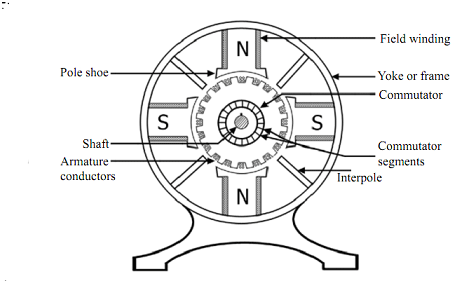
The main parts of DC Machine (motor or generator) are as follows:
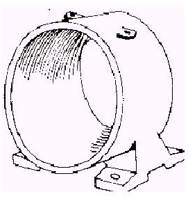
1. Yoke
- Function
- It provide mechanical Support for poles
- It also provide protection to whole machine from dust, moisture etc.
- It also carries magnetic flux produced by the poles
- Yoke is also called as frame.
- Material used
- For small M/C yoke is made of cast iron.
- For large M/C it is made of cast steel or rolled steel.
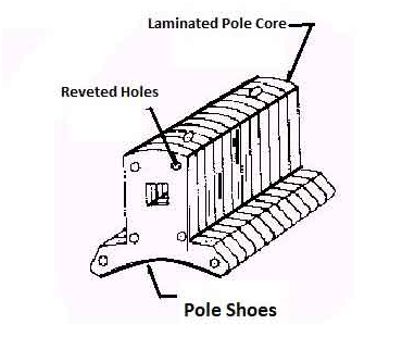
2. Pole & Pole core
- Function
- Pole of a generator is an electromagnet.
- The field winding is winding over pale.
- Pole provides magnetic flux when field winding is excited.
- Material used
- Pole core or pole made of cast iron or cast steel.
- It built of these laminations of annealed steel. The laminations is done to reduce the power lose due to eddy currents.
3. Pole Shoe
- Function
- It is extended part of pole. It enlarge area of pole
- Due to this enlarged area, flux is spread out in the air gap and more flux can pass through the air gap to armature.
- Material used
- It is made of cast iron or cast steed.
- It built of this lamination of annealed steel. the lamination is done to reduce power loss due to eddy currents
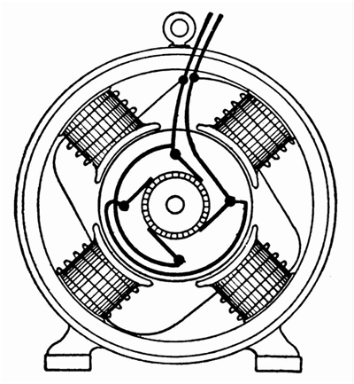
4. Pole coil or field windings
- Function
- It is wound around pole core and called as field coil
- it is connected in series to from field winding
- When Current is passed through field winding it electro magnetize the poles which produce necessary flux.
- Material used
- The material used for field conductor is copper.
5. Armature Core
- Function
- It has large number of slots in its periphery
- Armature conductor, are placed in this slots
- It is also provide path of low reluctance to the flux produced by field winding
- Material used
- High permeability low reluctance materials such as cast or iron are used for armature core.
- The lamination is provided so as to reduce the loss due to eddy current.
6. Armature Winding
- Function
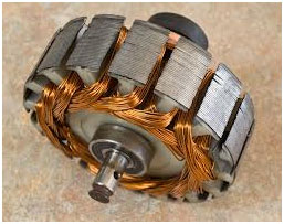
- Armature conductor are inter connected to form armature Winding
- When armature winding is rotated using prime mover. the magnetic flux and voltage gets induced in it
- Armature winding is connected to external circuit
- Material used
- It is made of conducting material such as coppers.
7. Commutator
- Function
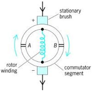
- It Convert alternating current induce in the current in a unidirectional current
- It collects the current form armature conductor and pass it load with the help of brushes
- It also provide unidirectional torque for dc motor
- Material used
- It is made of a large number of edge shaped segments of hard drawn copper.
- The Segments are insulated from each other by thin layer of mica.
OR
- The Segment of commutator is made of copper and insulating material between segments is mica.
8. Brushes
- Function
- Brushes collect the current from commutator and apply it to external load.
- Brushes wear with time and it is should be inspected regularly.
- Material used
- Brushes are made of carbon or graphite it is rectangular in shape.
