Author Archive
Working of Static Relay
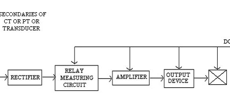
The primary of C.T. is connected to transmission line and secondary is connected to some filter circuit. This filtered signal is given to rectifier where it is converted from AC into DC (Electronics equipments works on
Microprocessor Based Overcurrent Relay

Current is taken from C.T. and given to I to V converter because many electronics circuit require voltage signal for operation. The A.C. voltage is converted into D.C. voltage by using rectifier. This D.C. voltage is proportional
Difference between static relays and electromagnetic relays
Points Static Relays Electromagnetic Relays Power consumption Very less 1 milliwatt High 2 watt Moving contacts No moving contacts. So, No problem of Arcing No needs to replace contacts. Moving contacts are present. Problem like Arcing, Replacement
Problems of circuit interruption
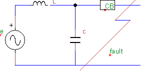
Following are the problems that occur when circuit breaker is clearing fault or CB starts operating 1.Rate of Rise of Restriking voltage (R.R.R.V.) Unit of R.R.R.V. is KV/Hsec Every line has some inductance L in series and
Block diagram of remote control system
Functions of each block of remote control system Remote control centre equipment consists Control panel with mimic diagram and control desk. Remote control switching equipments. FMVFT (Frequency modulated voice frequency telegraph. Power supply for control room. Mimic
What is Capacitance?
Capacitance of capacitor A capacitor is a passive electronic component that stores energy in the form of an electrostatic field. In its simplest form, a capacitor consists of two conducting plates separated by an insulating material called
What is difference between MCB and MCCB
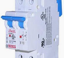
What is the difference between MCB & MCCB, Where it can be used? MCB stand for Miniature Circuit Breaker MCCB stand for Moulded Case Circuit Breaker MCB is miniature circuit breaker which is thermal operated and use
How to Electrical winding step by step
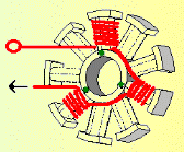
Electrical winding Step One Choose stator side with 3 points. Use 2mm wire and fold it double. Leaving 10cm as lead wire, start winding clockwise. Electrical winding Step Two Wind 16 turns on the first tooth, with
Difference between power transformers and distribution transformers
Those transformers installed at the sending or receiving end of long high-voltage transmission lines are the power transformers. The distribution transformer (generally pole mounted) are those installed in the localities of the city to provide utilization voltage
Power Formulas for AC and DC Circuit
Following are the Power Formulas in AC & DC Circuit Sr. Description Formula 1 Power in DC Circuits P = V X I P = I2 X R P = V2 / R 2 Power in AC