Author Archive
Difference between drift current and diffusion current

Drift current Diffusion current Under the action of electric field the charge carriers in the semiconductor material stops moving randomly and start drifting towards or away the applied electric field depends upon their nature. This drift of
Application and advantages of sensors
Sensor Advantages Disadvantages Applications Limit Switch sensors High Current Capability Low Cost Familiar “Low-Tech” Sensing Requires Physical Contact with Target Very slow response Contact bounce Interlocking Basic End-of-Travel sensing Photoelectric sensors Sensor all kinds of materials Long
Difference between AC Servo Motor and DC Servo Motor
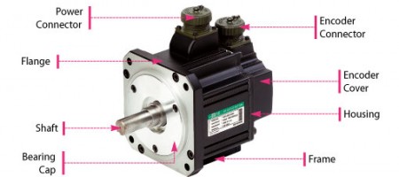
Following are main difference between AC servo motor & DC servo motor A.C. Servo Motor D.C. Servo Motor Low power output of about 0.5 W to 100 W. Deliver high power output. Efficiency is less about 5
Power Factor Correction
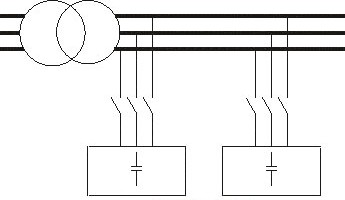
Capacitive Power Factor correction is applied to circuits which include induction motors as a means of reducing the inductive component of the current and thereby reduce the losses in the supply. There should be no effect on
Features for different types of circuit breakers
Factor Oil Breaker Air Breaker Vacuum/SF6 Safety In oil breaker circuit risk of explosion and fire due to increase in pressure during multiple operations In air breaker emission of hot air and ionized gas to surroundings In
Difference between Shunt Capacitor and Series Inductor Filter
Following are the difference between shunt capacitor and series inductor filter: Parameter Shunt Capacitor Series Inductor Place of filter Across the load In series with load Useful in Reducing ripple in load voltage Reducing ripple in load
Difference between Synchronous Motor and Induction Motor
Synchronous Motor Induction Motor Synchronous motor construction is complicated. Induction motor construction is simpler, particularly in case of cage rotor. This is Not self starting. This is self Starting Separate DC source is required for rotor excitation.
How to find Amp (Amperes) in ac and dc
E = Voltage I = Amps PF = Power Factor Eff = Efficiency HP = Horsepower Formula for finding Amperes when Horsepower is known in direct current (dc) and alternative current (ac): To Find (Formula) Direct Current
Difference between BJT And JFET
BJT JFET Unipolar device (current conduction is only due to one type of majority carrier either electron or hole). Bipolar device (current condition, by both types of carriers, i.e. majority and minority-electrons and hole). The operation depends
Types of Transformers Based on the Value of K
Transformation Ratio (K) The transformation ratio for voltage is defined as the ratio of secondary voltage to the primary voltage of a transformer. It is denoted by K. Turns Ratio of the Transformer The turn’s ratio of